Showing posts with label RV Mods. Show all posts

Saturday, 27 January 2018

Forest River 2401R Stereo Upgrade

Our RV came with the upgraded head unit from Jenson and while it did work as intended it was far from premium and the included GPS unit left a lot to be desired. It served us for our first year of ownership, but with our planned tour of North America this summer something better was required.
After a lot of research, I decided to replace it with an Android Head unit which turned out to be an easy and very worthwhile upgrade.


The Sprinter dash comes apart in layers, you have to slowly remove the trim pieces to gain access to the fasteners which makes it possible to remove the next layer till you can finally remove the stereo. All of the fasteners are either the same length T25 Torx screws, plastic tabs, spring clips or molded hooks. I just had to take my time gently removing them.


Once I had the radio removed I spent some time labeling all the wiring of which there are a lot.


The replacement unit was from Joying and only required a little modification to mount it.


Once the I doubled checked the new wiring harness and checked to make sure everything was working as it should it was time to finish the install.


The finished product looks as good as the original and works far better with the ability to use numerous Android apps and the GPS using both North American as well as Glasnost satellites for a faster and more accurate fix


Share:

Saturday, 6 January 2018

Mopeka LP Tank Check Sensor on a Horizontal RV Tank

My motorhome has 2 LP tank gauges both showing different readings, I had heard about a new way to monitor your LP tank using an ultrasonic sensor by Mopeka. It sounded like just what I needed but when it arrived, I discovered that while it works great on vertical tanks it's less than ideal on horizontal tanks like the kind that come on most class C RV's.

The problem is it's designed to mount on the flat part of the bottom of a vertical tank which a class C  with it's horizontally mounted tank causing the bottom of the tank to be rounded makes for a poor fit and not very accurate readings.

Fortunately, I have access to a 3d printer and after a few trial and errors in designing the case came up with a solution that works great.


 With the addition of a couple of zip ties to secure it to the tank, I now have a reliable sensor that will alert me before I run out of propane.


Share:

Thursday, 11 May 2017

Solar Install

My wife and I like to camp in areas that usually do not have hookups, so Solar was a requirement on this RV. After a lot of research on Solar setups, we settled on a system from AmSolar and I'm glad we did. While their kits may not be the cheapest, they are of very high quality and the instructions provided as well as there amazing customer service and available information on their website made me confident I could install this.

My Solar install consisted of

  1.  AmSolar 100W Complete Charger (Deluxe) Kit
  2. 2 additional SF 100 Panels (will be adding a 4th at a later date)
  3. Nature Power 2000 Watt Inverter with remote switch
  4. 2 Trojan T105 225Ah batteries (will have to modify the battery box to accommodate extra height)
1. The first thing did is figure out were to place all the components, and how I was going to run all the wiring before mounting anything. This is the layout I chose for the solar panels with the remaining panel I plan on adding going in the empty space at the top.


   Combiner Location
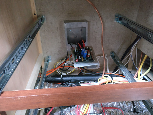
   The empty space behind my Convenience Panel is the perfect place to bring my Solar wires into
   the RV from the roof, then down the side of the refrigerator to the Solar Controller. AmSolar's
   Combiner Box is designed to allow you to drill a hole thru the roof to run your cables while
   ensuring that no water can get inside.  I could also modify the box and just bring the wires
   thru the fridge vent but I would still have to drill into the RV and reseal those holes so I
   chose to bring the wires into the space behind the Convenience Center, drilling a pilot hole from
   the inside out, once I determined roughly where the hole would be on the roof.

   Control Panel
   Bedroom Wall or Step Well

   Solar High Current Switch
   In Step Well

   Solar Controller 30 Amp Circuit Breaker and Shunt
   Mounted in Battery Box in Stairwell within 18" of Batteries

2. Remove all drawers from the right side of RV to make running wires easier
    Remove sealant around propane lines by step well to run wiring to the battery box.


3. Install Solar Controller under Kitchen Cabinet on inside Exterior Wall.


4. Installed control panel on bedroom wall by TV mount location  run RJ-11 control wire to solar
   controller and 18/2 signal shunt wiring to the battery compartment. (red positive shunt wire goes
   to shunt terminal that is attached to battery negative terminal.)


5. Install Solar Panel Disconnect Switch in Step Well.


6. Run power cables from charge controller to battery box as well as temp sensor wire.


7. Install combiner box on roof run cables to Solar Controller. In order to do this, I removed the convenience center in order to access the space behind it.


Then after checking everything twice to verify I would not be drilling into anything. I drilled a 1/8 pilot hole up thru the roof after climbing back up on the roof I found that I was 2" away from where I thought I would be an even worse I missed drilling thru a bundle of wire by 1 mm boy did I feel lucky.


8. Install panels using alcohol, wiping one way only to ensure the feet stick properly, cures to 50% in       10 minutes takes 3 days to fully cure.


Since the VHB tape will be compromised on the pebbled fiberglass roof, mark foot location then using a scotch pad scrub foot location to remove high spots and ensure the area is clean then use isopropyl rubbing alcohol to clean clean clean the area, wiping in one direction only - set panel in place.

After allowing feet to set ( I waited 3 days) I applied 3M 5200 all around the foot and 1/2" on all sides this really is just extra insurance as after the 3 day setup period I could not move the panels at all. The 3M 5200 takes 7 days to fully cure.

9  Wire panels and run wiring to the combiner box. Make sure to keep panels covered as they will produce electricity even on cloudy days mine still showed a voltage of 7 volts, even with the cardboard covering it.


10.  Final wiring and checks. Once the panels were mounted I finished the controller and high current switch wiring. I probably should have done this first but was not sure were the combiner box would end up. The wiring was straightforward negative PV wire to the controller positive PV wire runs first to the high current switch so you can turn the panels off then to the controller. Battery wires run from the battery box to the controller positive wire runs thru a 30 amp circuit breaker mounted in the battery box.


Once that is done all that is left is to turn on the controller breaker program the controller then turn on the panels and enjoy all that free energy.


Share:

Sunday, 30 April 2017

Forester MBS 2401R Battery Upgrade

As part of my Solar installation, I needed to upgrade my batteries. I would have liked to go to LiFe PO4 but could not justify the cost, so I went with less expensive Trojan T105's in order to do this I had to modify my battery compartment raising it 1 1/2" to make room for the added height of the Trojans.

This is what I started with


Due to the extra width of the Trojans, I had to relocate the existing circuit breakers.


Using 2X2 lumber I built a frame around the existing battery compartment.


Then installed the batteries. An added benefit of doing this is my wiring is much neater and maintaining the batteries is much easier.


Share:

Thursday, 13 April 2017

Fantastic Fan Upgrade - Adding a Reverse Switch


My RV came with two Fantastic Fans which pleased me but neither had the ability to reverse direction, after spending some time searching on the Internet I found out it was possible to purchase upgrade kits to add that function but the cost, at over $100.00 just didn't make it worth it.

So I researched a little harder and found out that with a cheap DPDT ON/ON toggle switch I could add that capability for a few bucks, so that is what I did.


Remove the 4 screws holding the square trim ring to the ceiling paying close attention to where the wires go.


Now to install the switch. I recommend you disconnect the battery or at the very least remove the fuse from the fan body just to be sure you don't short something out along the way. After removing the fuse, remove the screws that hold the vent assembly to the ceiling and gently lower it and let it hang by the wires.


Once the vent body is hanging by the wiring, figure out which wires you need to disconnect from the fan to remove the body. On my units, it was a red and a white wire coming from the fan unit I cut them to the length of the red wire making sure I had room to connect to the switch I was installing in the left corner.

Once that was done I had to disconnect the black wire attached to the fuse and the white wire attached to the circuit board so I could remove the vent assembly.

Then I cut the hole for the toggle switch and attached the positive and negative wires to the switch as per the diagram.


All that remains is to add connectors to the  2 wires coming from the fan, reconnect the black wire to the fuse and the white one to the control board. Install the connectors to the remaining middle terminals and bolt everything back together and enjoy your reversible fan.


Share:

Popular Posts

Powered by Blogger.